For this proceedure to work, the trailer frame must have no permanent crossmembers in the way of the swing keel trunk. The trailer undercarriage (axles, etc.) must be removable.
A 6" x 2" x 10' steel girder was installed in the attic of the garage. This beam was supported by two steel columns at one end, and a concrete wall at the other. A 2-ton come-along winch, chained to the beam in the attic, was used for all lifting and turning operations in the garage.
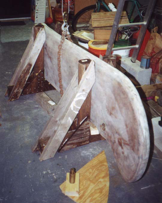
Figure 1. Catalina 25 swing keel in 4x4 support fixtures, chain lifting sling attached to hoist.
In preparation for handling the keel away from the suspended come-along, a plywood pallet was fabricated, and PVC rollers were cut to length. The four rollers were 6" SCH40 PVC 30" long. The pallet was 2' x 8' plywood 1-1/2" (10 layers) thick. The 1-1/2" plywood was made by cutting a 3/4" x 4' x 8' panel lengthwise and bonding it back together with lots of WEST epoxy and dozens of 1-1/2" wood screws for clamping pressure. Before the pair of 2' x 8' panels were glued together, they had holes cut in them as follows. In the top layer, 1" rope holes were drilled at all 4 corners, and oval hand holds about 1-1/2" x 6" were cut a couple of inches in from the edge at the midpoint of the two long sides. In the bottom layer, large relief cutouts were made around the locations of all the holes in the top layer.
The holes and cutouts:
Once the keel was ready to install, it was lifted out of the stationary support fixtures, and those fixtures were moved out of the way. The keel was then lowered back down, and tilted so that it lay flat on top of 4" x 4" blocking. The lifting bridle chain was repositioned, and the keel was then relifted in the horizontal, or flat, orientation.
- Allow getting a hand hold on the empty pallet, which of course weighed about as much as a full sheet of 3/4" plywood.
- Provide places to Attach ropes for dragging the loaded pallet around, should the need arise.
- The relief notches allow room to get ropes and/or pry bars under the loaded pallet should it ever manage to get flat on the concrete. (Never let a heavy load get flat on the floor!)
The 2' x 8' pallet was positioned on top of heavy wooden blocking, and more blocking was placed on top of the pallet to spread the weight of the keel, and to keep it from rocking. The blocking under the pallet was stacked tall enough to allow a 3-ton automotive floor jack to fit under the pallet. The keel was then lowered onto the pallet, and the lifting bridle and hoist removed. The automotive jack was used to lift one end of the pallet at a time, and the blocking under the pallet was replaced with the PVC pipe rollers (aimed out the garage door). After the first rollers were in place, and before the pallet was lifted off the last of the blocking, the wooden wheel chock wedges were shoved under the rollers to prevent the whole thing from taking off on its own on the slightly slanted garage floor.
Once all the blocking under the pallet had been replaced with rollers, the wheel chocks were moved a few inches toward the open garage door, the rollers started rolling, and the keel headed downhill with considerable determination. Remember to use those chocks!
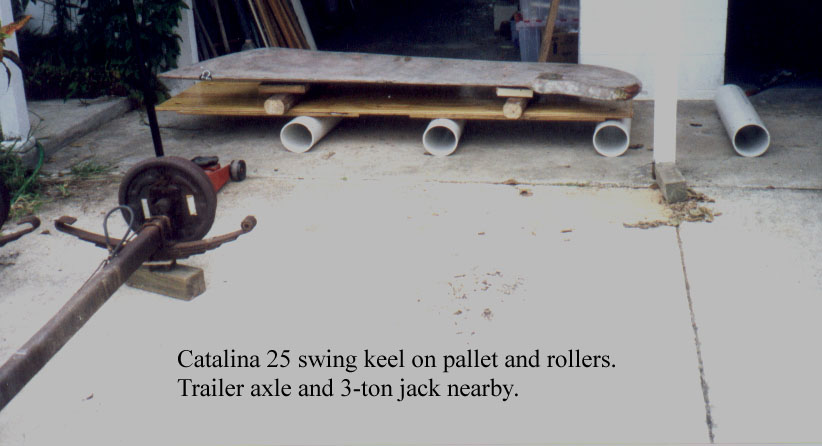
Figure 1. Catalina 25 swing keel on pallet and rollers. (Trailer axle and 3-ton jack nearby.)
As each roller came out from under the trailing edge of the pallet, it was moved to the front and rolled under again. To negotiate turns, the rollers were inserted at an angle. For tighter turns, the pallet was lifted slightly with the jack, one end at a time, and the rollers angled while still under the pallet.
Let's be clear that the plywood and pipe described were just barely up to the task of moving the 1,500 pound keel on smooth, nearly level concrete. Don't even think about using anything even a tiny bit weaker for this job. The plywood creaked, groaned, and flexed something fearful. The PVC rollers distorted into clearly oval cross section under the weight.
Figure 2. Catalina 25 swing keel on pallet and rollers being moved under jacked up boat and trailer.
Another "tool" that proved handy was a pair of wooden wedges about 2" x 2" on one end, 6" long, and tapering to a point at the other end. These were used as wheel chocks under the pipe rollers to prevent accidental movement.
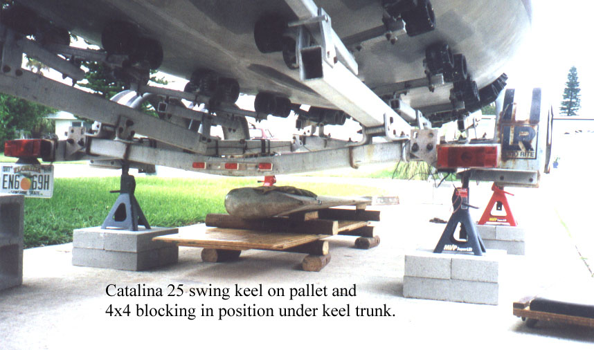
Figure 3. Catalina 25 swing keel on pallet and 4x4 wooded blocking in position under keel trunk.
Once the keel was in position under the trailer, centered under the swing keel trunk, the pallet was jacked up and the rollers were replaced with wooden blocking.
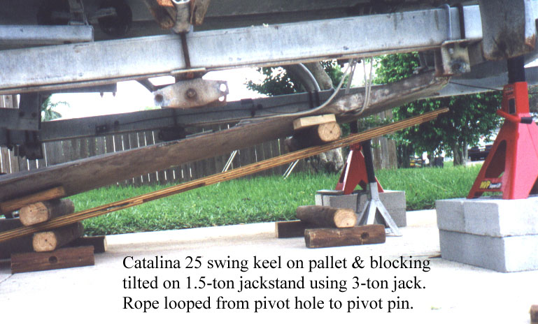
Figure 4. Catalina 25 swing keel on pallet and blocking tilted on 1.5-ton jackstand after lifting with 3-ton jack. Rope looped from pivot hole to pivot pin.
The keel pivot pin and bearing blocks were installed in the hull (without the keel). The forward end of the keel and pallet were lifted as high as safe and practical with the jack. A 3/8" nylon rope was then looped around the pivot pin in the hull and through the pivot hole in the keel so that there were four standing parts supporting the load, all free to shift around the pin, and so even out the strain among them. A jackstand was then used to support the forward end of the pallet in the tilted position. (Never trust any part of your body to a hydraulic jack, especially one with wheels -- they'll turn on you when you least expect it.)
Figure 5. Catalina 25 swing keel on pallet and blocking tilted on 1.5-ton jackstand. Slack removed from rope looped from pivot hole to pivot pin, and from attached keel lifting cable.
Next the boat's swing keel winch cable was attached to the old style eyebolt loosely threaded into the aft end of the keel. It's very important to note that the eyebolt was loose, and rotated 1/4 turn from the normal alignment. This was done to provide a fair lead for the winch cable with the keel on its side. The slack in the winch cable was then taken up, but without lifting the keel yet.
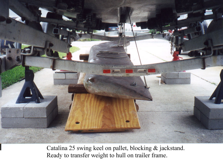
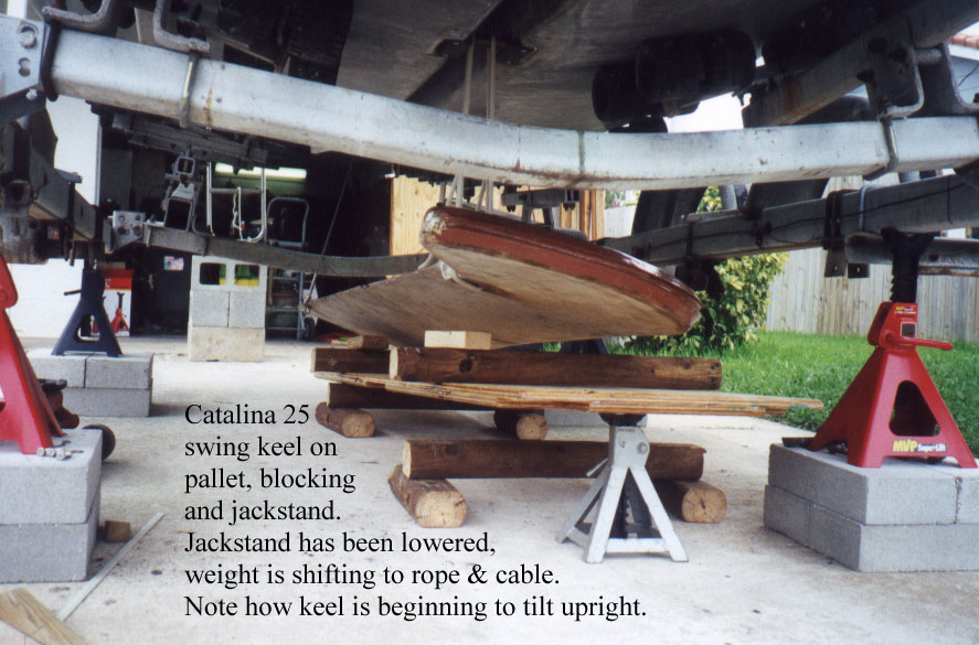
Figure 6. Catalina 25 swing keel on pallet blocking, and jackstand. Jackstand has been lowered, weight is shifting to the rope and cable. Note how keel is beginning to tilt upright.
Next, the jackstand at the forward end of the pallet was lowered so that the weight of the forward end of the keel was being supported by the rope at the keel pivot. Then the swing keel winch was used to slowly lift the weight of the aft end of the keel off the pallet. As the keel continued tilting toward the upright position, the loose eyebolt pivoted in the keel, maintaining a fair lead for the winch cable.
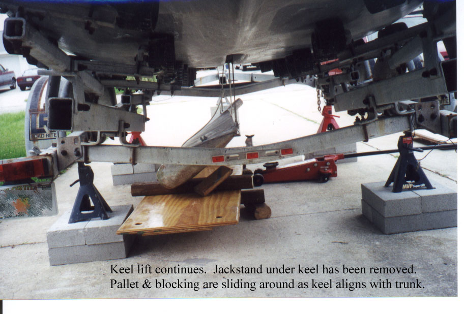
Figure 7. Keel lift continues. Jackstand under keel has been removed. Pallet and blocking are sliding around as the keel aligns itself with keel trunk.
As the weight of the keel began to transfer from the pallet and blocking to the hull and trailer frame, the keel began to align itself with the swing keel trunk. This caused the pallet and blocking to shift. Keep this in mind when deciding where to position the supports under the trailer frame. Don't give the keel an opportunity to knock the trailer off its supports! Also be careful not to pull the aft end of the keel tight up against the bottom of the hull at this point in the proceedure, as a sudden unexpected shift of the keel could damage the hull, keel cable, winch, and/or winch supports in the boat.
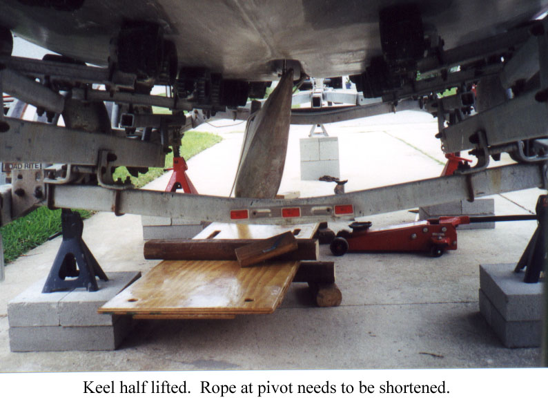
Figure 8. Keel half lifted. Rope loop at pivot ready to be tightened.
Once the aft end of the keel was lifted up near the hull, the foward end of the keel was lifted as close as practical to the pivot pin using the 3-ton jack, and the rope loop was shortened as tight as possible. It was necessary to lift the ends of the keel in steps, first one end then the other, until the keel was hanging free under the boat, supported by the winch cable at the aft end, and the shortened loop of rope at the forward end.
Figure 9. Swing keel hanging free. Foward end of keel was lifted with 3-ton jack, and rope loop around keel pivot pin shortened.
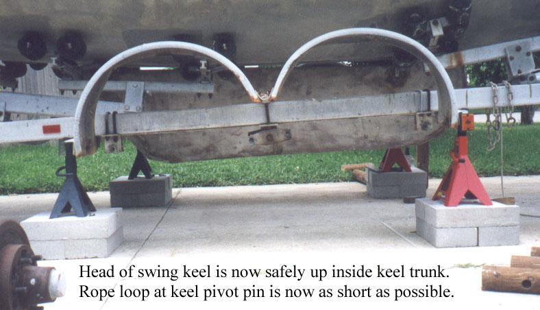
The keel was lifted high enough that the head of the keel was up inside the keel trunk with the rope loops and pivot pin supporting the weight forward. Then the aft end of the keel was lifted as high as possible.
Figure 10. Head of swing keel entering keel trunk. Rope loop at keel pivot shortened as tight as possible.
The 3-ton jack, backed up with wooden blocking, was used to lift and support the forward end of the keel while the rope was removed.
The pivot pin and bearings were then unbolted from the hull and moved to the keel. Next, four 3/8"-NC x 18" threaded stainless steel rods were passed through the bolt holes in the bearings, and screwed as far as possible up into the threaded inserts for the pivot bearings in the hull. The rods were tightened by jambing two nuts together on the lower end of each rod and turning them with a 9/16" wrench. Also included on each threaded rod shishcabob were several split washers just under the bearings (to fill the counterbores and provide some load sharing cushioning), a couple of greased flat washers as thrust bearings, and a bronze nut which could be used to lift or lower the keel on the rods. The rod threads were lightly greased between the bronze nuts and the hull.
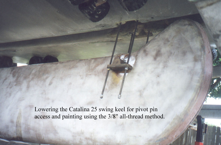
Figure 11. Lowering and raising Catalina 25 swing keel for painting access and pivot pin maintenance using the 3/8" all-thread method.
At this point in the keel installation procedure, with the keel hanging under the boat suspended from four threaded rods and the winch cable, bottom paint was applied to the keel trunk and the portion of the keel which would be up inside the trunk once installation was complete.
The keel was then lifted into final position in the head of the keel trunk using a combination of jacking, blocking, lifting and pivoting with the keel winch, and tightening the bronze nuts on the threaded rods. I should note that it was far from necessary to combine all these methods at once to do the final lifting and positioning of the keel, but I wanted to see how the methods compared. The hydraulic jacks were the fastest but the most scary, and required the most skill. Turning the nuts on the threaded rods with an open end wrench was very tedious but secure. Using the winch and blocking to seesaw the keel up seemed like a good compromise between speed and safety.
Once the pivot bearings were all the way up against the hull and held tightly by the nuts on the threaded rods, one by one the rods were released, removed, and replaced with the longest stainless steel bolts that would tighten up on the bearings before running out of thread. I'm not going to specify a length here because I suspect there are too many variables to guarantee that one size fits all. Before installation, the shank and threads of each bolt were coated liberally with polysulfide sealant. As I recall, both flat and lock washers were used.
Once the pivot pin installation was complete and secure, the aft end of the keel was lowered as far as possible (to a thin block of wood on the the concrete). The cable was released from the keel, and the eyebolt was removed. The new, improved cable to keel attachment hardware from Catalina Yachts was installed using bedding compound and lots of torque. Once again, the longest bolt possible was used. I had drilled and bottom tapped the 1/2"-NC hole in the keel deep enough to use about a 1-1/2" to 1-3/4" bolt.
This article has addressed installing the swing keel, not reconditioning and preparing the keel for installation. Obviously the lift bolt hole in the keel deserves very close attention during periodic haul out inspection and preventative maintenance, especially if the keel is out of the boat.
Also not covered here is the small matter of getting the boat and trailer up off its axles and onto heavy duty jackstands atop concrete pedestals. Since every trailer and work site is going to be different, I won't attempt to explain that in detail. However, here are a few general notes that might be helpful.
In getting the trailer undercarriage out of the way, plan on cutting or breaking just about every fastener you remove. Have replacements in hand before you start. Don't assume, without checking, that you know where to find them, or that they're inexpensive.
Jackstand advertised ratings are wildly optimistic. Don't bet you boat or your life on some marketing flack's fantasies. I used two 6-ton stands under the trailer frame just ahead of the keel trunk, two 3-ton stands under the aft end of the trailer behind the keel trunk, and another 3-ton stand under the trailer tongue. Be really, really sure the trailer is solidly supported before removing the wheels and undercarriage. Once you think you've got it up solid, try to knock it down. Try hard, now's the time to find out. The concrete blocks I used under the jackstands held up fairly well. One of the solid ones cracked into two or three pieces, but continued to hold things up. One of the hollow type concrete blocks failed rather spectacularly while I was setting up the stands with the wheels still on the trailer. Loud scary noises, concrete shards and dust flying. I stopped what I was doing and bought more of the solid ones.
I found that I needed between 35" and 40" clearance between the bottom of the keel trunk and the concrete for working clearance. There needs to be a carefully thought out compromise between too low to maneuver the keel, and so high that the boat, trailer, and stands get wobbly. Wobbly is bad, very bad.
When you've reinstalled the undercarriage and wheels, and are removing the last of the stands and blocking, take a moment to verify that the trailer wheels are chocked. Please don't ask me why I included this note.
When handling heavy weights, have just enough level headed help around to get you out of trouble, or to call for more help if they can't. Don't make a party out of it. Especially no kids, they're like little unpredictable bundles of Murphy's law just waiting to strike.
Be aware of your local ordinances regarding projects of this nature in a residential setting. Let your neighbors know in advance what you're up to. Reasure them that you're not crazy or suicidal.